CSF Charge-Air Cooler Manifold Machined Billet - Toyota A90 A91 Supra (2020+)

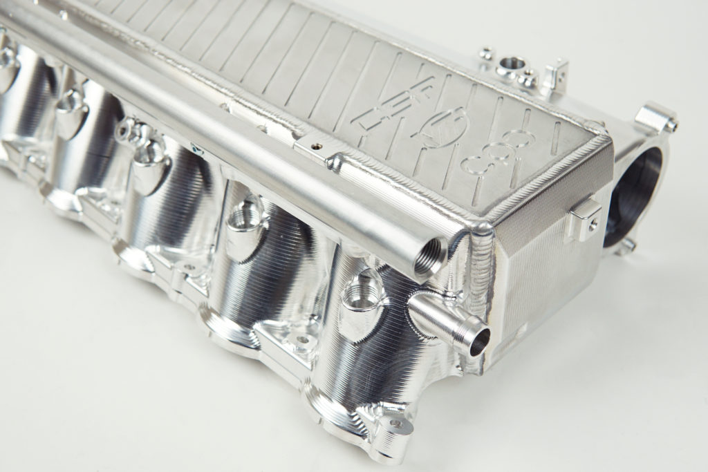
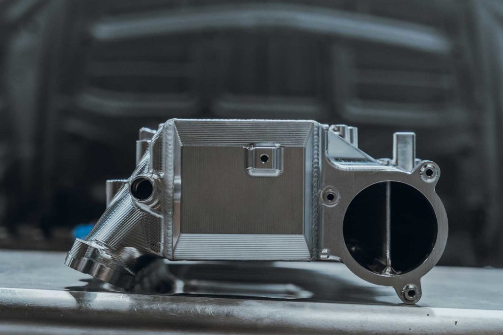
CSF is proud to announce its most advanced cooling system to date – the new Charge-Air Cooler Manifold for A90/A91 Toyota Supra and BMW G-Series (B58). With well over 1,500 hours of design, prototype development, machining, and testing, CSF, along with partners VF Engineering (USA) and Custom Plenum Creations (Australia), has now brought a state-of-the-art CNC machined, high-performance Charge-Air Cooler Manifold to the...
CSF is proud to announce its most advanced cooling system to date – the new Charge-Air Cooler Manifold for A90/A91 Toyota Supra and BMW G-Series (B58).
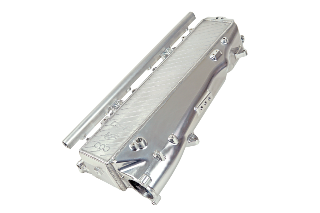
With well over 1,500 hours of design, prototype development, machining, and testing, CSF, along with partners VF Engineering (USA) and Custom Plenum Creations (Australia), has now brought a state-of-the-art CNC machined, high-performance Charge-Air Cooler Manifold to the B58 platform for Mk5 Supra and BMW models. This product solves what has been commonly known as a weak link of an otherwise impressive new engine platform.
With the larger and more efficient water-to-air intercooler performance, lower pressure drop across the system, included fuel rail, kit for top feed port injection, and several other industry-leading features, the CSF Super Manifold will allow B58 owners to maximize the performance of their vehicles and push the limits further than what has been previously possible with this new platform.
CSF’s Creates the Missing Link to Maximum B58 Performance
The newer 2nd gen B58 engine, found in the Mk5 Supra, has already been proven to be an incredible platform for performance enthusiasts – taking the performance and motorsports industry by storm in just a couple of years since its release. In a short amount of time, performance enthusiasts have already started to more than double the stock engine output – now pushing through 700whp, 800whp, and looking into the elusive 4 digit 1,000whp mark.
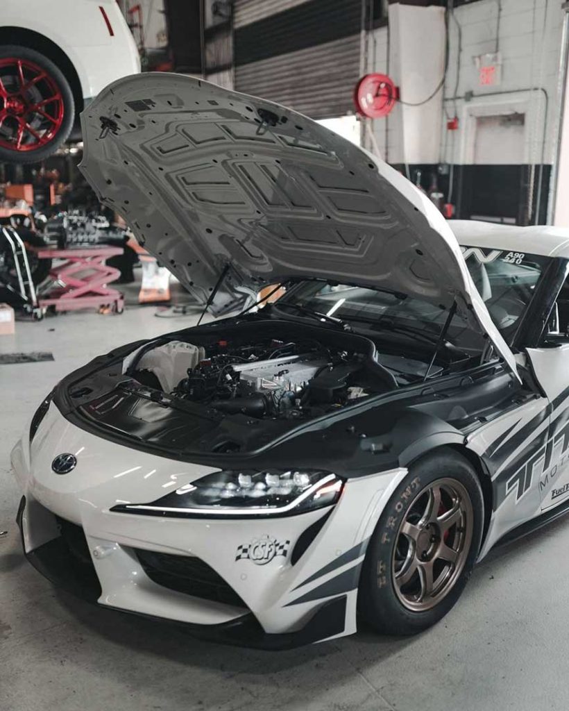
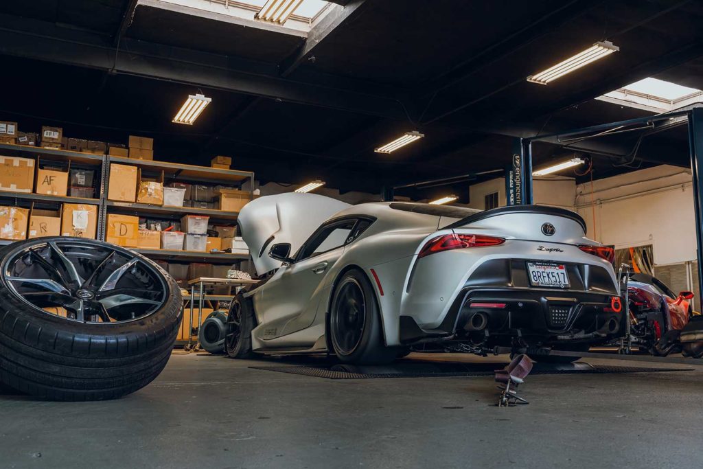
World-leading Supra specialist and CSF R&D partner, Titan Motorsports, putting the new manifold to the test, along with the full range of CSF Cooling products for the MK5 Supra (5-Piece Ultimate-Spec Cooling Package).
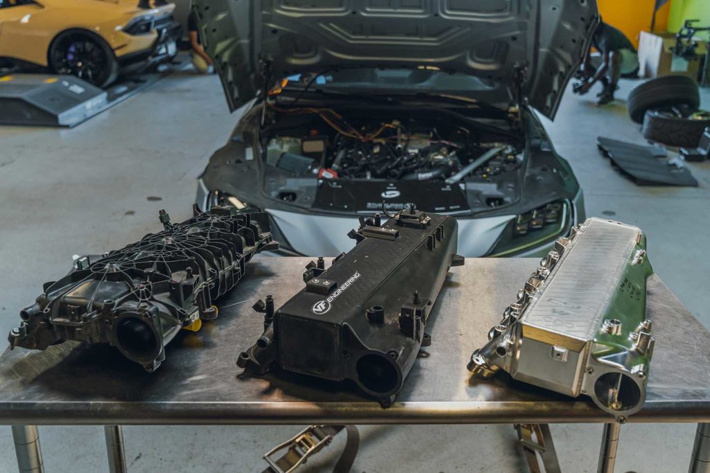
The OEM water-cooled charge air cooler intake manifold for the B58 engine is adequate in cars with little or no modifications, but starts to really show an apparent weakness in cars that have bolt-on modifications, turbo upgrades, increased fueling (such as port injection), and performance tuning. Also, the OEM intercooler system has been known to suffer from heat soak in demanding racing conditions such as time attack, endurance racing, drag racing, and drifting, as well as spirited driving on the street. This can cause the car to pull timing out of the engine due to high intake air temperatures (IATs), and then can cause “limp mode” once temperatures reach a certain threshold, as the vehicle’s ECU will cut power to protect the engine.
Design & Engineering
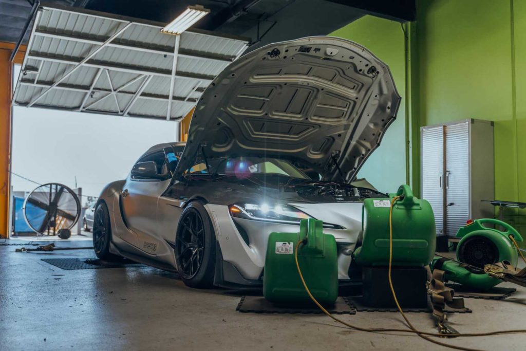
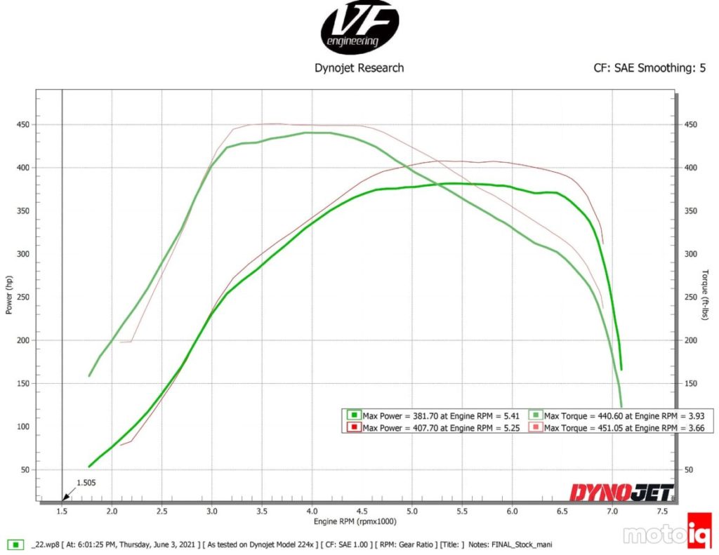
CSF conducted extensive testing on the dyno with R&D partner VF Engineering to ensure performance improvements before going into production with the new manifold. We performed over 50 dyno runs on the same car, on the same day, in relatively hot ambient conditions (~90°F) comparing the performance of the CSF Charge-Air Cooler Manifold to the OEM. Both the CSF and OEM cooler went through roughly 25 back-to-back dyno pulls every 30 seconds to measure the performance of the car overtime, resistance to heat soak, recovery time, and the effect on the turbo system duty cycle.
Local R&D partner and contender for both BimmerChallenge and the TRD Time Attack Series, Studio RSR, has been working with CSF and testing the new manifold off and on the track.
Reputable automotive website and performance part testing specialist, MotoIQ, was on site to witness and assist in organizing the testing to validate the accuracy of the claims made by CSF on the improvements and benefits of the upgraded manifold. The results were published independently by MotoIQ and are now available on their website – read the article here for more specific details on the increased performance of the CSF B58 upgraded intake manifold.
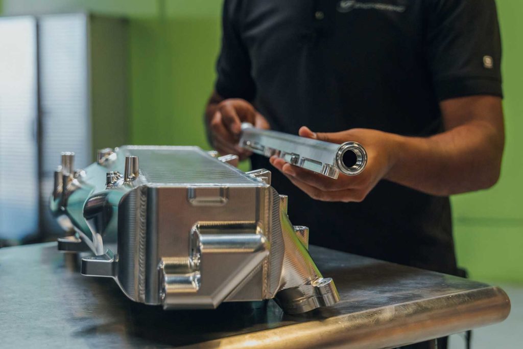
Ravi, owner of CSF Racing & High-Performance, along with Nik, owner of VF Engineering, go over all the details with owner of MotoIQ and industry legend, Mike Kojima.
Summary of Testing
- Faster recovery of intake air temperatures
- ~30°F reduction of intake air temperatures (IAT’s) compared to OEM
- Less pressure drop compared to OEM core
- Puts less stress on the turbo system, allowing more boost to be made at higher targets
- Avoided going into limp mode after prolonged demanding conditions, simulating motorsports use
- On a stage 2 car with bolt-on upgrades, making ~400whp, comparing dyno run 19 between CSF and OEM, an increase of ~26whp and 11wtq were achieved
- The performance increase and delta between CSF and OEM will be bigger as power is increased in the vehicle
INTERESTINGLY ENOUGH, THE CSF/VF MANIFOLD HAD MUCH LOWER INLET TEMPERATURES, RIGHT ABOUT 230 DEGREES OR 30 DEGREES COOLER THAN THE STOCK MANIFOLD WHILE THE OUTLET TEMPERATURES WERE ABOUT 6 DEGREES COOLER, UNDER 125 DEGREES. THERE IS A LOT MORE TO THE DATA THAT FIRST MEETS THE EYE. THE LOWER INLET TEMPERATURES ARE AN INDICATOR THAT THE RESTRICTION TO AIRFLOW ACROSS THE CORE IS MUCH LOWER. THIS IS TO BE EXPECTED OF THE LARGER FRONTAL AREA OF THE CORE. WITH LESS INTAKE RESTRICTION, THE COMPRESSOR OF THE ENGINE’S TURBO IS RUNNING MUCH FARTHER AWAY FROM THE SURGE LINE IN A MORE EFFICIENT AREA OF THE COMPRESSOR MAP. WITH GREATER EFFICIENCY, THE TURBO IS HEATING THE INTAKE AIR A LOT LESS. SINCE THE COMPRESSOR IS WORKING MUCH MORE EFFICIENTLY, THE TURBINE DOESN’T NEED TO RECOVER AS MUCH POWER FROM THE EXHAUST STREAM TO PRODUCE THE SAME BOOST AND THUS THERE IS LESS BACKPRESSURE. THIS IN TURN INCREASES THE ENGINE’S TOTAL VOLUMETRIC EFFICIENCY. THIS IS A SYNERGISTIC CASCADE THAT WILL INCREASE POWER AND REDUCE STRAIN ON THE ENGINE AND ITS COMPONENTS WHICH HAS A MUCH MORE PROFOUND IMPACT THAN JUST LOWER INTERCOOLER OUTLET TEMPERATURES.
MIKE KOJIMA, OWNER OF MOTOIQ.COM
For more testing results, visit MotoIQ.com
To jump straight to the testing results including graphs for water temperature, air temperature, and more details, click here.
You asked, CSF listened – All the Features You Need to Push the Limits
Several months ago, during the final design stage of CSF’s new manifold, owner of CSF, Ravi Dolwani, hopped on a plane to Texas to attend the TX2K drag race invitational. Included at this year’s event was an A90 Supra class. Ravi went to speak with Supra owners and find out what they wanted out of an upgraded performance manifold. He came back to CSF following the race weekend, and worked with long time design partner and CSF customer, VF Engineering, to implement a host of features that took the performance benefits and capabilities of the new CSF manifold to an even higher, industry-leading level.
Individual Nitrous / Methanol Injector Ports
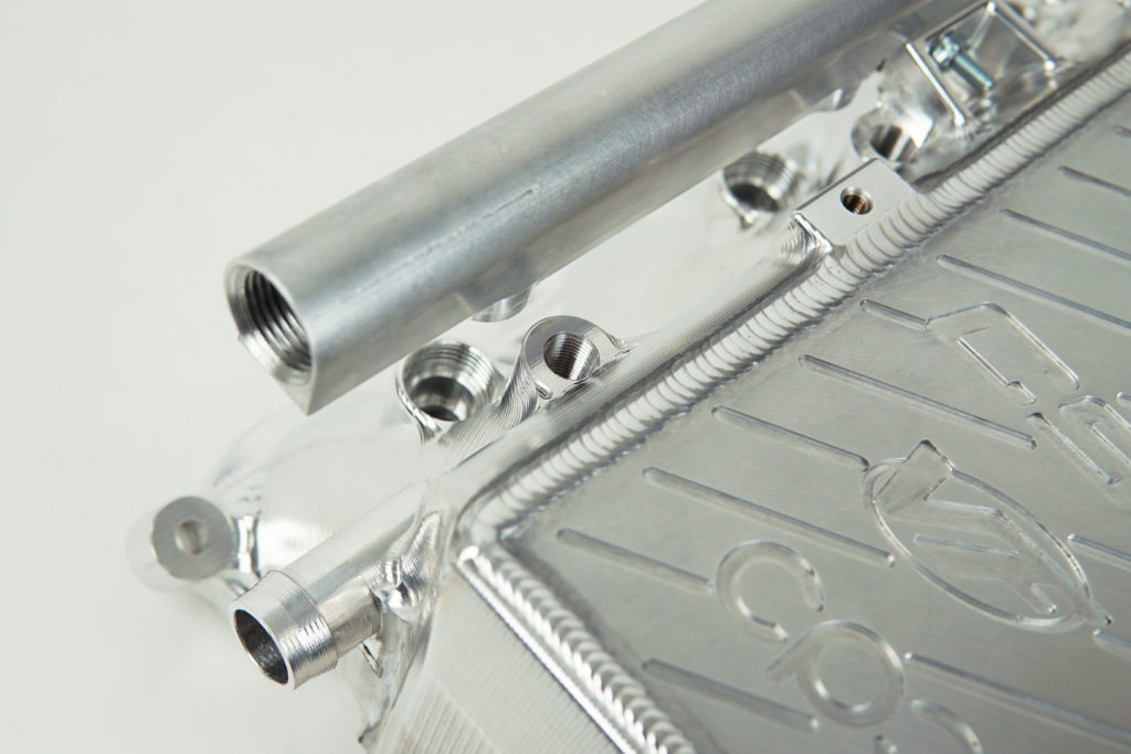
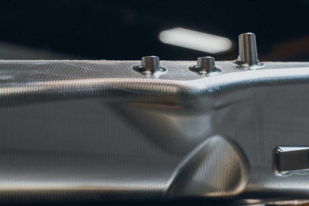
On the outlet tank, each cylinder runner has a 1/8th NPT port which can be used for nitrous or methanol injection (a popular power modification on the B58 engine). The CSF manifold allows for maximum spray control and even spray distribution throughout the engine. A nitrous system set-up specifically for the CSF manifold will be coming soon from industry leaders Nitrous Express.
A handful of cars at TX2K had blown their engines due to the way their nitrous systems were plugged into their vehicles. With the OEM plastic manifold, a single spray system is most commonly used as threading into plastic to insert an injector node is already very difficult to install properly. The single fogger system, more often than not, will create unequal distribution of spray in the engine, either giving some cylinders too much or too little spray. This will increase the chance of severely damaging the engine.
Top Feed Port Injection with Included Fuel Rail
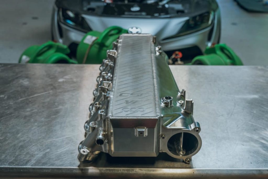
An extruded fuel rail is included with the CSF manifold. It can be attached to the outlet side of the manifold. The AN-8 fuel rail comes with feed and return -8 internal hex plug fittings from Radium Engineering for a plug and play installation.
- Fuel rail aperture for each cylinder is an optimized 7mm opening for compatibility with most commonly used high performance injectors
- CSF recommends using Injector Dynamics (ID) injectors for the best performance – the most commonly used injector for this engine has been ID model # 1050.34.14.14.6 (qty 6)
- Anodized CNC machined injector hats (qty 6) are included in the supplied hardware kit to accommodate short height injectors aka “shorties”
Vacuum and Parameter Pad
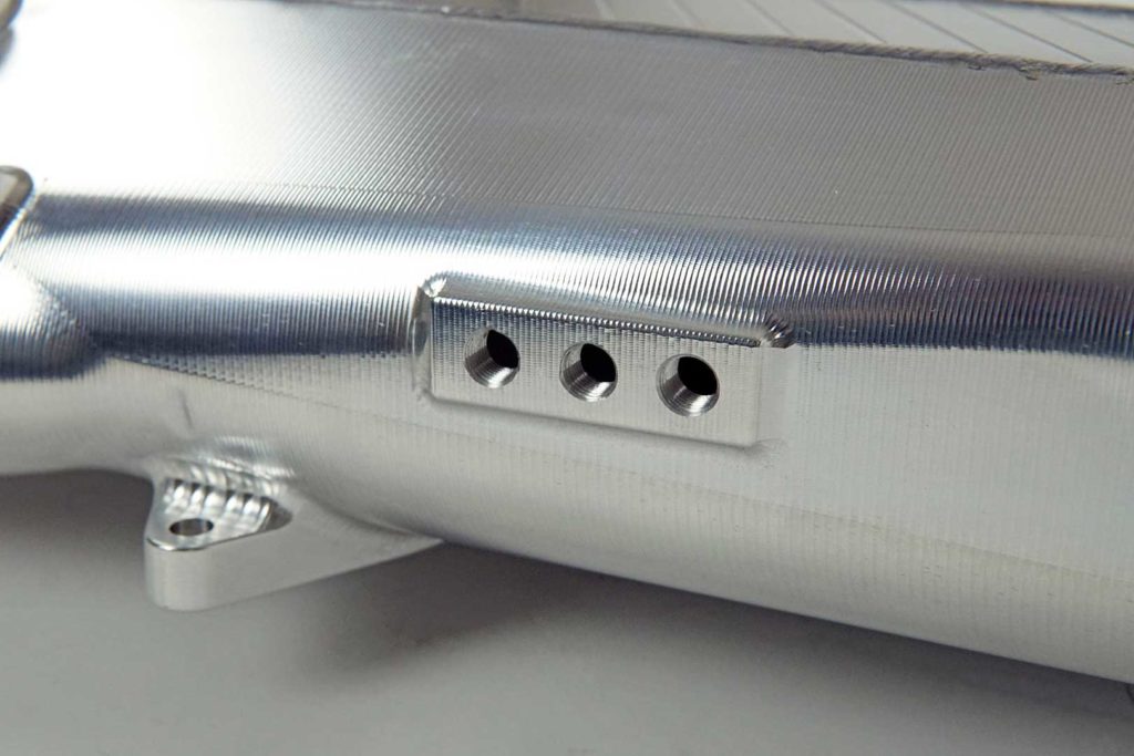
On the side of the manifold inlet, CSF has included a 3 port pad into the machining of the tank. This can be used to measure additional parameters or as an additional vacuum source. These three 1/8th NPT ports can be plugged with the included hardware kit if they are not used.
Easy Access to Spin-Off Oil Filter With Counter Balanced Design
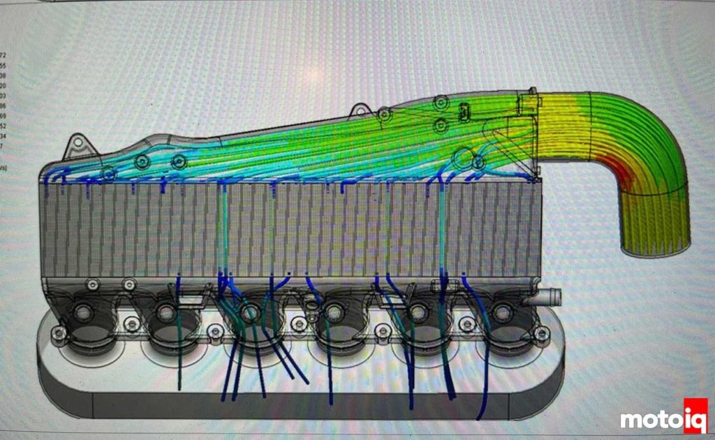
Imagine having to remove your manifold every time you wanted to change your oil, especially if your vehicle is used in motorsports where oil changes occur more often. CSF thought of its customer base during the design phase and have incorporated a recessed design towards the back of the manifold that for allows easy access to the spin-off oil filter. A counter balanced design protrusion above the recess was simulated in SolidWorks CFD software to ensure smooth air delivery into the rear of the core for the best possible cooling effect.
Air Inlet Divider
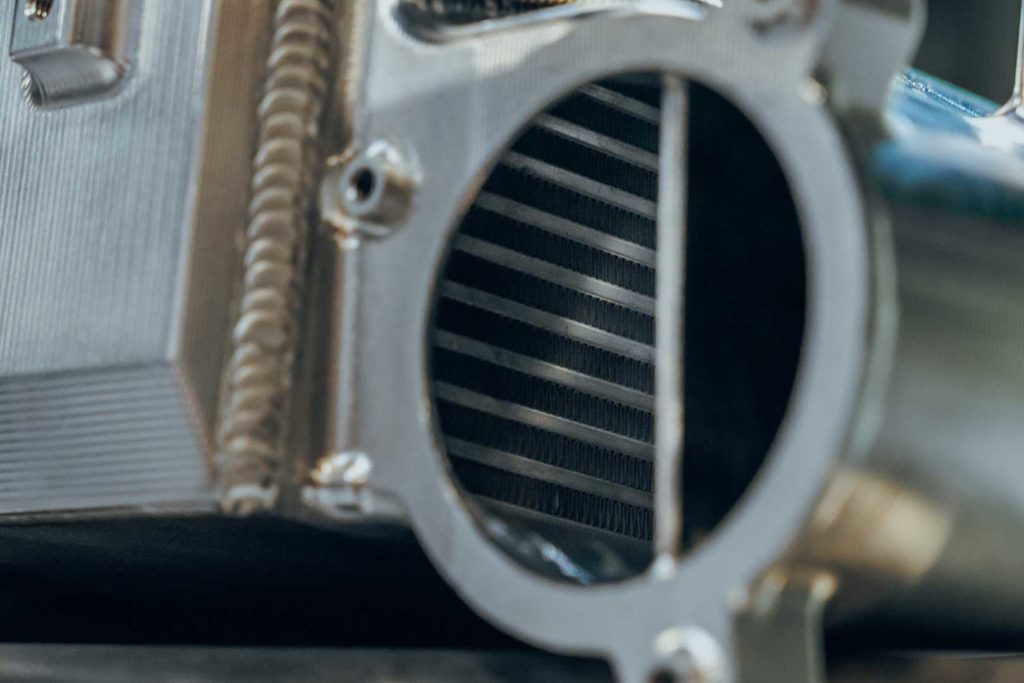
Another exclusive feature of the CSF manifold is the inclusion of an air divider welded into the inlet side tank of the manifold. With the length of the design, the engineers at VF Engineering wanted to make sure that the volume and velocity of air received to the back of the manifold to cylinder areas four, five, and six would be equal to the airflow passed through the front half of the manifold for cylinders one, two, and three. After extensive simulations in SolidWorks CFD software, an air divider was added to the design to ensure the best possible and equal cooling performance to each cylinder of the engine.
CFD analysis in SolidWorks during the R&D phase of the design
Breather Ports for Inlet/Outlet of Water Tanks
Two 1/8th NPT ports are located on the top of the back water plate. These can be used to measure inlet/outlet water temps as well as used as breather ports to help in the bleeding procedure to ensure all air has been cleared from the water system. 1/8th NPT plugs come included in the supplied hardware kit. Please follow OEM BMW or Toyota bleeding procedure which takes roughly 15 minutes to complete.
Hardware Kit, Well Thought-Out Instruction Manual & The Ability to Install OEM and OEM-Style Engine Covers
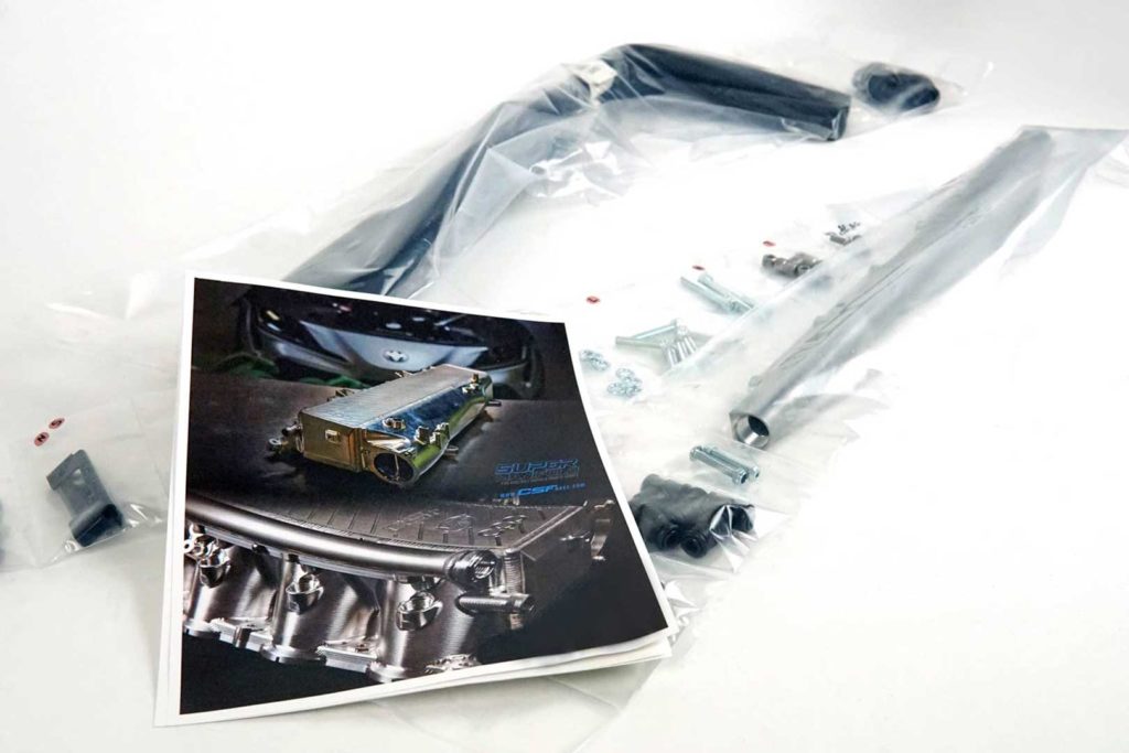
Included in the supplied hardware kit is several brackets, bolts, washers, and mounting posts to be able to install the OEM and OEM-style engine covers. This is an industry-exclusive feature to the CSF x VF Engineering design, and was extremely difficult to not only engineer, but to manufacture as well. An array of items come vacuum packaged with corresponding letters listed on an easy to use Bill-of-Materials List (BOM) along with exploded diagrams and a simple order of operation procedure list to follow for installation. Made with racers and DIY enthusiasts in mind.







![CSF High Performance All Aluminum Radiator - Black - Subaru WRX [VB] (2022+)](http://www.circuitspecr.com/cdn/shop/files/7224B_2_500x500.jpg?v=1741924723)
![CSF High Performance All Aluminum Radiator - Black - Subaru WRX [VB] (2022+)](http://www.circuitspecr.com/cdn/shop/files/7224_1_500x500.jpg?v=1741924723)
![CSF High Performance All Aluminum Radiator - Silver - Subaru WRX [VB] (2022+)](http://www.circuitspecr.com/cdn/shop/files/7224_5_500x500.jpg?v=1741924649)


